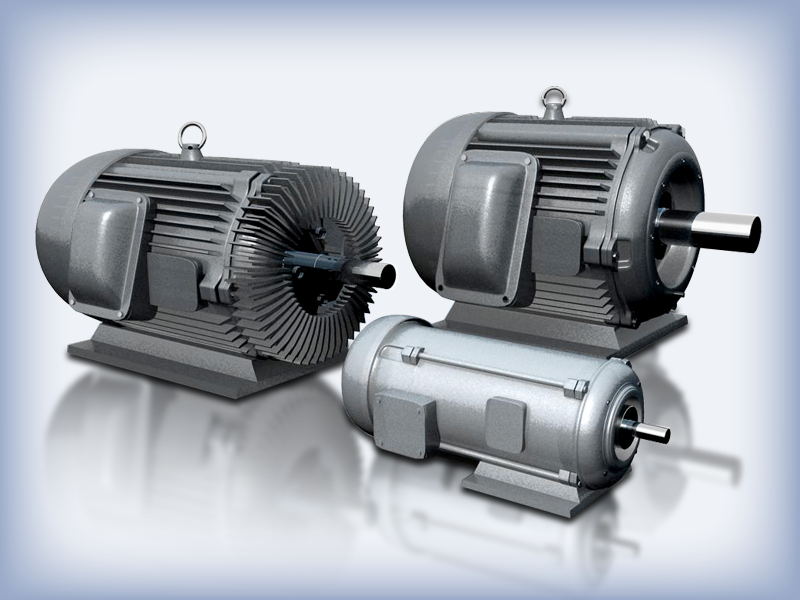
Motor starters provide the simplest function, they start the motor. A starter can be as simple as a single contactor, or very complex using multiple contactors and relays. Described here are some of the common types of starters and their operations.
Motor starters generally fall into two categories: full voltage or reduced voltage. The choice of which type of starter to use depends on various factors, such as the current carrying capacity of plant wiring, the ability of plant power supplies to absorb power transients, the size of the motor, and other special control requirements.
Full Voltage Starter
Full voltage starters, sometimes referred to as across-the-line starters, are the most widely used type of starter. A starter of this type directly connects the motor leads and line leads together, through either a manual starter or the main line contacts of a magnetic starter, and does not provide any means of reducing the applied voltage or limiting the starting current. The full voltage starter is used on almost all three-phase, squirrel cage, and single-phase machines.
Reduced Voltage Starter
A common function of reduced voltage starters is that they reduce the starting current of induction motors. Whenever the starting of a motor at full voltage causes serious and unacceptable voltage transients or unneeded, excessive torque, reduced voltage starters are used to reduce the starting transients. The excessive torque could put a tremendous strain or shock on motor parts, including gears, fan blades, pulleys, and couplings.

Speed Control
Many applications require a motor with a variable number of speeds and some method of speed control. Speed control occurs with the use of control devices that regulate the startup and operating speed of a multi-speed motor. This is accomplished with operator control of a semiautomatic controller to control a motor start sequence.
Squirrel cage motors do not generally lend themselves very well to speed control. Semiautomatic control of speed may be accomplished with multi‑speed, squirrel cage motors by having the operator select the proper speed required to meet the load or speed specifications.
When true variable speed is required, other options must be considered, such as a wound rotor motor with secondary control, an adjustable speed AC commutator motor, or an AC motor with applied frequency control.
Control Power
Every control circuit of any machine that is controlled either semi-automatically or automatically actually has two separate power circuits. The main power circuit supplies power to the machine being controlled, such as a motor or heater, and the control power circuit supplies power to the control devices that make up the controller.
The most common method of supplying control power is by tapping the main power either directly or through a transformer. This allows the control circuit to be energized anytime power is available to supply the load. Another method to supply control power is the use of a power supply that is altogether separate from the main power. Control power supply schemes, such as this, are used when it is desirable to have a more reliable control power supply than the primary power supply to the load.
The expert consultants at Technology Transfer Services are well versed in everything motors, from starters to motor control strategies, and are available to help ensure that the equipment in your facility is well maintained and running efficiently. Give us a call today to talk to one of our consultants: (813) 908-1100, or learn online at odesie®.

