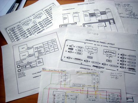
A schematic diagram is a drawing that shows physical components in their proper positions within a system, but not necessarily in their actual physical location. Electrical diagrams are the most commonly used drawings. The block diagram, one-line diagram, elementary diagram, and wiring diagram follow an order from very broad to very specific. These diagrams are designed to illustrate a system with very simple drawings and then work their way up to the required specifics. The purpose of this organization is to make the job easier; for example, a problem can be isolated to a block, traced through a one-line diagram, and then repaired using a wiring diagram.
The following are the most common types of electrical diagrams:
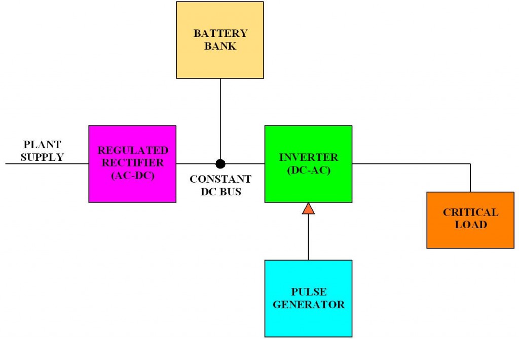
Block Diagram – A block diagram shows the major components of electrical or mechanical interrelations in block, or square or rectangular, form. The lines between the blocks represent the connections between the systems or components. With electrical block diagrams, a single line may represent one wire or a group of wires. The block diagram introduces a system as a whole, conveying the general operation and arrangement of the major components.
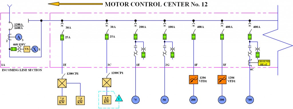
Single Diagram – A single, or one-line, diagram indicates, by means of single lines and standard symbols, the paths, interconnections, and component parts of an electric circuit or systems of circuits. It provides a basic understanding of how a portion of the electrical system functions in terms of the circuit’s physical components.
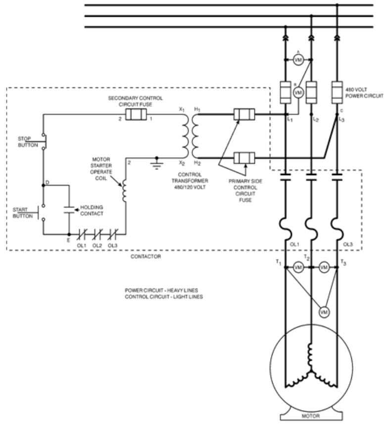
Elementary Diagram – An elementary diagram, or schematic, is a drawing that falls between one-line diagrams and wiring diagrams. They are used to show the wiring of instrument and electrical control devices in elementary ladder or schematic form. Elementary diagrams reflect the control wiring required to achieve the operation and sequence of operations described in logic diagrams.
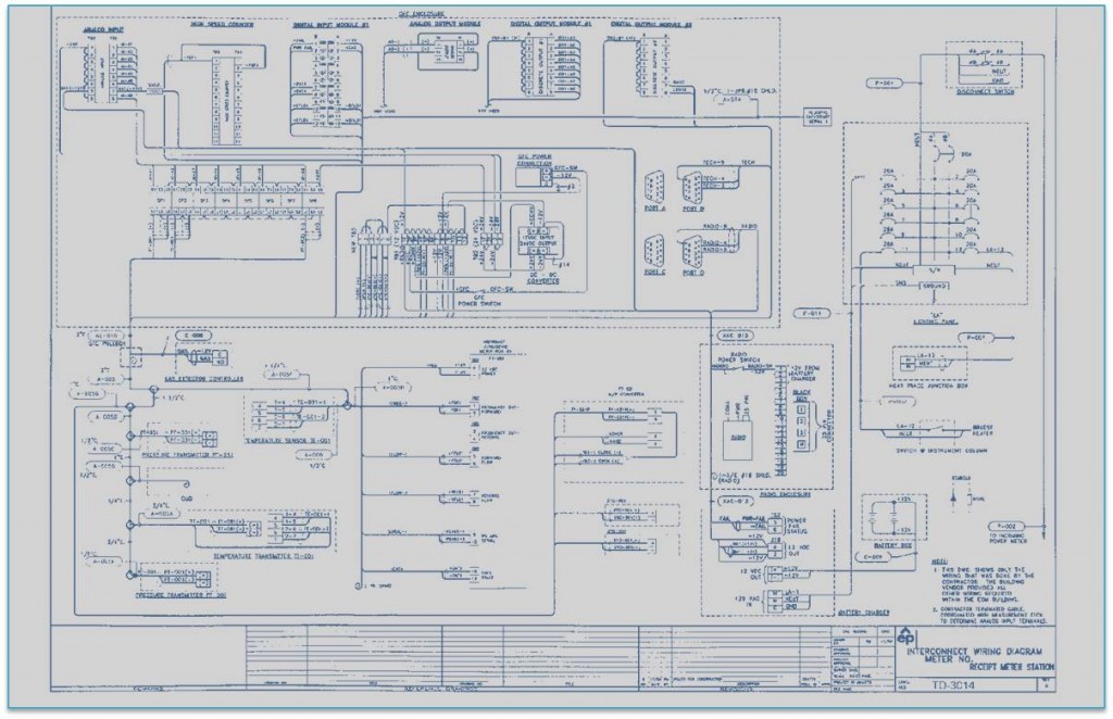
Wiring Diagram – A wiring diagram is usually used for troubleshooting systems. Wiring diagrams show the relative position of the equipment’s various components as well as how each conductor is connected in the circuit. These diagrams are classified in two ways: internal diagrams, which show the wiring inside a device, as in a vendor supplied diagram for a recorder, and external diagrams, which show the wiring from the component to the rest of the system.

