The operation of a PLC is very simple. The processor makes decisions based on a ladder logic program written by the user. In order to use the program properly, the PLC must communicate with the various field devices it is tasked with monitoring and controlling. It then compares the actual conditions of the field devices with what the program instructs them to do, and updates the output devices accordingly.
Operational Sequence
The operational sequence is as follows:
- Input switch is pressed.
- Input module places a “1” in the input data table,
- The ladder logic program sees the “1” and caused a “1” to be put into the output data table.
- The output data table causes the output module to energize associated point.
- The output device energizes.
The Scan Cycle
PLCs operate by continually scanning programs and repeat this process many times per second. When a PLC starts, it runs checks on the hardware and software for faults, also called a self-test. If there are no problems, then the PLC will start the scan cycle. The scan cycle consists of three steps: input scan, executing program(s), and output scan.
Input Scan: A simple way of looking at this is the PLC takes a snapshot of the inputs and solves the logic. The PLC looks at each input card to determine if it is ON or OFF and saves this information in a data table for use in the next step. This makes the process faster and avoids cases where an input changes from the start to the end of the program.
Execute Program (or Logic Execution): The PLC executes a program one instruction at a time using only the memory copy of the inputs the ladder logic program. For example, the program has the first input as ON. Since the PLC knows which inputs are ON/OFF from the previous step, it will be able to decide whether the first output should be turned ON.
Output Scan: When the ladder scan completes, the outputs are updated using the temporary values in memory. The PLC updates the status of the outputs based on which inputs were ON during the first step and the results of executing a program during the second step. The PLC now restarts the process by starting a self-check for faults.
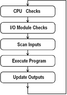
Figure 1: PLC Scan Cycle
Logic Scan
Ladder logic programs are modeled after relay logic. In relay logic, each element in the ladder will switch as quickly as possible. Program elements can only be examined one at a time in a fixed sequence. The ladder logic scan begins at the top rung. At the end of the rung, it interprets the top output first, and then the output branched below it. On the second rung, it solves branches, before moving along the ladder logic rung.
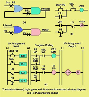
Figure 2: PLC Logic Scan
For detailed information on PLCs, visit our free Industrial Wiki or contact us at sales@techtransfer.com to set-up a class at your facility.